
Design of binary subtractor using MSI ICs
IC 74LS83 is a 4-bit parallel binary adder chip. It adds/subtracts a four-bit number (nibble) with another 4-bit number. The block symbol for the IC is shown in Fig.1. This IC has two sets of 4-bit inputs along with a carry input C0. It performs binary subtraction on the A & B inputs and the carry input C0. It generates a 4-bit Difference and a Borrow out C4.
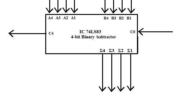
Fig. 1 Block Symbol of four-bit Subtractor IC
A circuit that can subtract 4-bit numbers can be designed using a control input and additional EX-OR IC 74LS86. For this we use the EX-OR gate as a "Controlled Inverter". The explanation for this concept can be easily understood from Fig.2. The four bit input B4, B3, B2 & B1 can be passed through the controlled inverter IC 74LS86 and the A4, A3, A2 & A1 are connected directly to A inputs of IC 74LS83 as shown in Fig 3.
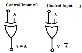
Fig.2. Exclusive-OR gate used as a Controlled Inverter
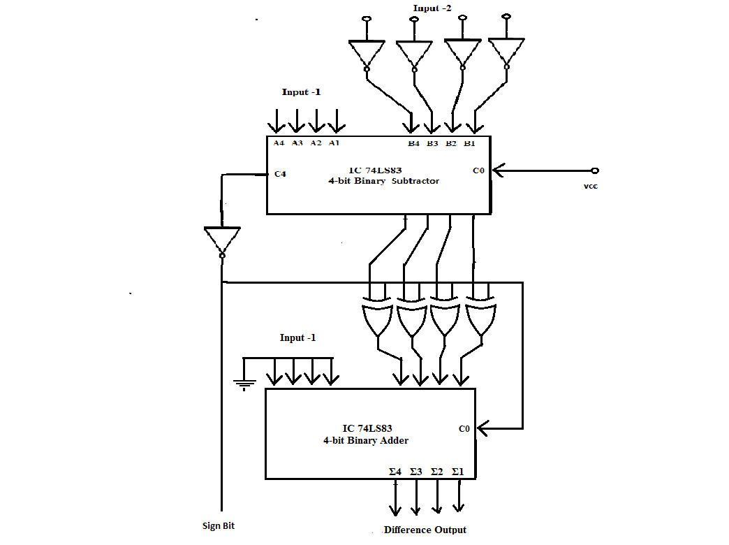
Fig.3. 4-bit Binary Subtractor
Four-bit Subtraction: When Control input is set = 1, the Carry-in input C0 = 1. In this situation, the Ex-OR gates will provide 1's complement of the Input-2 to the B-inputs of Adder IC. Moreover as C0 = 1, the addition of 1 to the 1's complement of B gives 2's complement of B. Now the IC 74LS83 adds Input-1 i.e. A4, A3, A2, A1 to the 2's complement of B and produces the Carry and Sum output on C4 & the lines Σ4, Σ3, Σ2, & Σ1.
Example 1: Let Input-1 = A4 A3 A2 A1 = 1001 & Input-2 = 0111 & control input be set to 1. 1's complement of 0111 = 1000. Since carry input C0 = 1, the input B becomes, B4 B3 B2 B1 = 1000 + 1 = 1001. Now IC 74LS83 performs addition of A & 2's complement of B and produces the output.
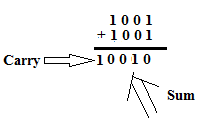
Since a Carry is generated discard the Carry and the Sum is the final output of subtraction operation. The result is Σ4 Σ3 Σ2 & Σ1 = 0 0 1 0.
Example 2: Let Input-1 = A4 A3 A2 A1 = 0111 & Input-2 = 1001 & control input be set to 1. 1's complement of Input-2 i.e. 1001 = 0110. Since carry input C0 = 1, the input B becomes, B4 B3 B2 B1 = 0110 + 1 = 0111. Now IC 74LS83 performs addition of A & 2's complement of B and produces the output.
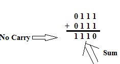
In this case no Carry is generated during addition. Hence the answer can be obtained by taking the 2's complement of the Sum output and attaching a negative sign. So the 2's complement of 1110 = 0010 and the final result of subtraction is Σ4 Σ3 Σ2 & Σ1 = - 0 0 1 0.
Numerical:
For subtracting two number, the 2's complement of one number is calculated and then added to other number
To calculate 2's complement of a number, the 1's complement of number is calculated i.e. number is represented in binary format, and then inverted. And then add 1 to it.
For eg.: Complement of 2 is:
2 => 0010
1's complement => 1101
2's complement => 1101 + 1 => 1110
Hence 2's complement of 2 is 1110.
Examples:
- 1. 4 - 0
2's Complement of 0 = 1 0000
| 0 | 1 | 0 | 0 | |||
|---|---|---|---|---|---|---|
| + | 2's complement of 0 | 1 | 0 | 0 | 0 | 0 |
| 4 | 1 | 0 | 1 | 0 | 0 |
(The MSB bit is complemented to achieve the Sign-bit)
Sign Bit = 0 (Positive Number)
- 2. 4 - 2
2's Complement of 2 = 0 1110
| 0 | 1 | 0 | 0 | |||
|---|---|---|---|---|---|---|
| + | 2's complement of 2 | 0 | 1 | 1 | 1 | 0 |
| 2 | 1 | 0 | 0 | 1 | 0 |
Sign Bit = 0 (Positive Number)
- 3. 2 - 4
2's Complement of 4 = 1100
| 0 | 0 | 1 | 0 | |||
|---|---|---|---|---|---|---|
| + | 2's complement of 4 | 0 | 1 | 1 | 0 | 0 |
| 14 | 0 | 1 | 1 | 1 | 0 |
Sign Bit = 1 (Negative Number)
As the output is negative number, it is in the 2's complement format. Hence the 2's complement of Answer need to be taken, to achieve the right answer:
Answer => 1110
1's Complement => 0001
2's Complement => 0001 + 1 = 0010
Hence, final answer = 0010 with Sign bit = 1