
Applications of Multiplexers
1.1 Introduction
Whenever there is a need to connect multiple input devices, one at a time, to a system, then a digital combinational circuit called multiplexer is useful.
1.2. Example 1: Implementation of 4: 1 Mux
The expression for the output Y in case of a 4:1 multiplexer is given as:
Y = A’.B’. D0 + A’. B. D1 + A. B’. D2 + A. B. D3
Or
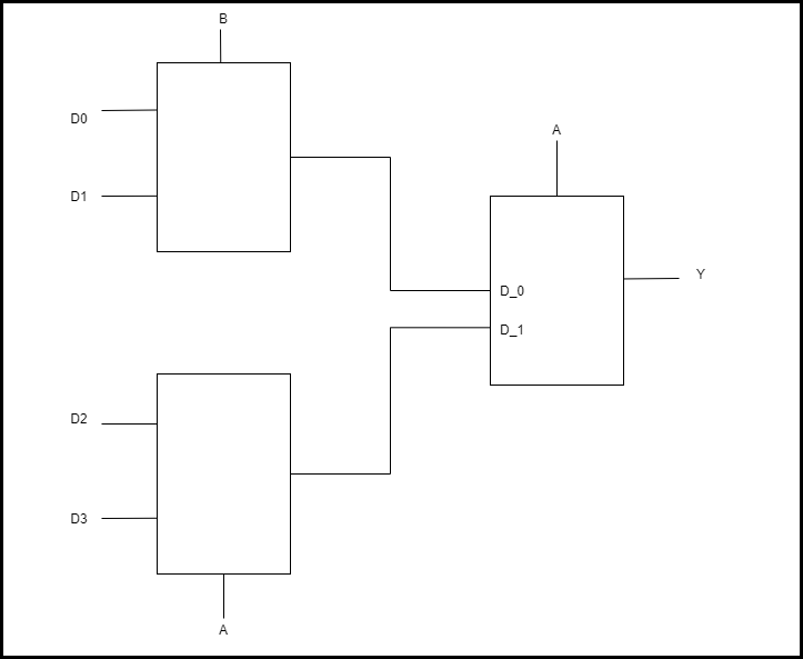
Y = A’.(B’.D0 + B.D1) + A.(B’.D2 + B.D3)
Construct the 4:1 mux as shown in figure Using simulator the circuit for 4:1 multiplexer can be constructed and verified.
Assignment: Realize the equation Y = A’.B + B’.C’ + A.B.C using a 4 -to- 1 multiplexer.
Solution:
There are three variables in the given equation. Let variables A & B be used as select lines and variable C as the data input D. Express Y as a function of minterms of three variables as shown:
Y = A’.B + B’.C’ + A.B.C
Y = A’.B + B’.C’(A’ + A) + A.B.C
Y = A’.B’.C’ +A’. B. 1 + A. B’. C’ + A.B.C --- (iv)
The logic equation for 4:1 Mux is:
Y = A’.B’.D0 + A’.B.D1 + A.B’.D2 + A.B.D3--- (v)
Comparing equations (iv) & (v),
D0 = C’, D1 = 1, D2 = C’ and D3 = C
Connection diagram:

Function Table:

Using simulator the circuit can be build and verified.