Multiplexers using Basic Logic Gates
1.1 Introduction
A digital multiplexer is similar to a multi-position switch with many inputs and only one output. It has control inputs to select a particular input. It is also called as a channel selector and abbreviated as Mux.
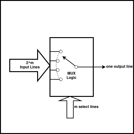
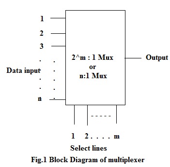
A multiplexer has m select lines, 2^m inputs and only one output as shown in the figure. Commercially, multiplexers ICs(integrated circuits) are available in powers of 2, e.g. 2:1, 4:1, 8:1 and 16:1 Mux.
| No.of select lines (m) | No.of inputs (2^m) | No. of Outputs Y | Multiplexer Type |
|---|---|---|---|
| 1 | 2 | 1 | 2:1 |
| 2 | 4 | 1 | 4:1 |
| 3 | 8 | 1 | 8:1 |
| 4 | 16 | 1 | 16:1 |
It is easier to build multiplexers using gates (small scale integration -SSI ICs) for a few select lines. But as the number of select lines increases, use of medium scale integration MSI ICs becomes the best choice. TTL IC 74LS150 is a 16:1 Mux. In this experiment design of smaller size Muxes are considered. A 2:1(read as 2 as to 1) multiplexer can be designed using: a. basic logic gates b. universal gates (NAND & NOR).
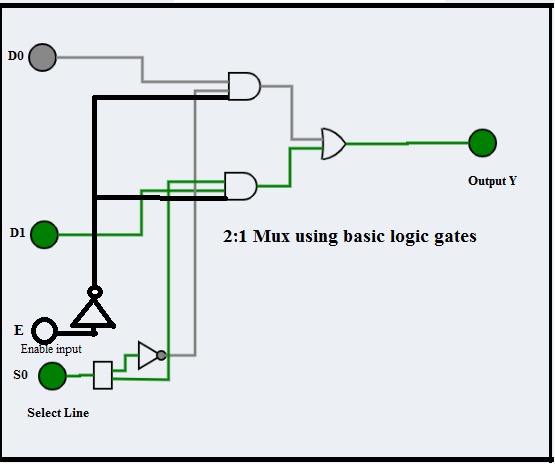
1.2.Example 1: Design of 2:1 Mux using basic logic gates
A simple 2:1 Mux will have 2 input lines D0 & D1 and one select line S0 and a single output Y.
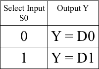
The select line can take a value either 0 or 1:
a. If S0 takes a value 0, the input D0 is selected and the output Y = D0.
b. If S0 takes a value 1, the input D1 is selected and the output Y = D1.
1.2.1 Theoretical Design:
The flow diagram explains the steps involved in the design of the circuit:
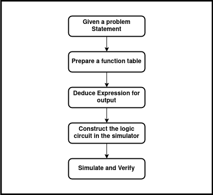
Apply these steps to design a 2:1 Mux using logic gates:
a. Prepare the function table of the 2:1 Mux:
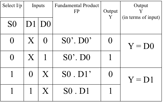
b. Formulate the expression for output Y by considering only those FPs for which the output is 1. Y = S0’. D0 + S0 . D1 The simplified function can be tabulated as:
c. Draw the logic diagram for the expression:
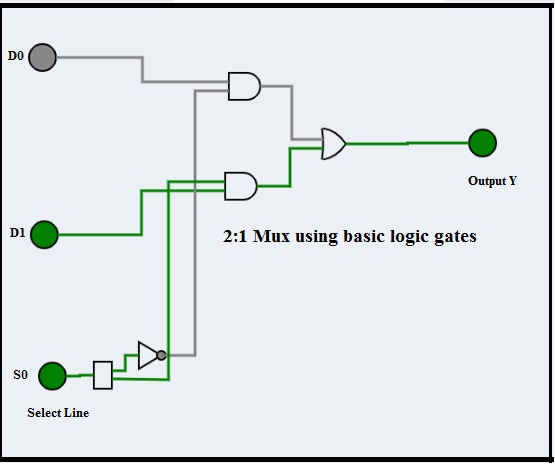
d. Using simulator construct the circuit and verify its operation.
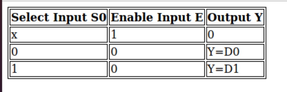
e. The same circuit can also be designed by having an active low enable input as shown in image.
The simplified function can be tabulated as:
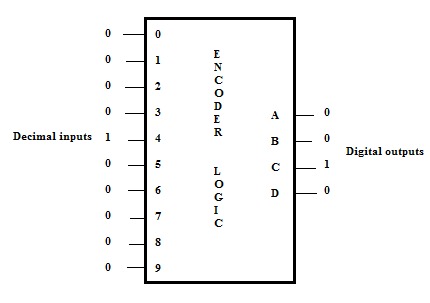
1.3. Encoder Logic
The figure shows the concept of encoder wherein input line 4 is high and all other inputs are low. The output of the encoder is a decimal 4, whose equivalent binary is 0100.
The concept of decimal to binary(10 to 4 binary) encoder is shown in the figure given below. On similar lines an octal-binary encoder will have eight inputs and produce 3-bit binary output.